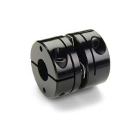

The 16 MM X 3/8" DISC COUPLING from Ruland Manufacturing (DCS26-16MM-3/8"-A) is a precision mechanical component designed to connect two rotating shafts while compensating for minor misalignments and transmitting torque. While not an electronic component in the traditional sense, its proper integration is critical to the performance and reliability of motion systems involving motors, encoders, and other driven elements on your PCB. Successful implementation requires careful consideration of the mechanical system's influence on the electronic drive and feedback circuits.
Recommended circuit topologies and design best practices begin with recognizing that this coupling is often used in servo or stepper motor systems. For servo systems, ensure your control loop (typically a PID topology) has sufficient bandwidth to manage the slight torsional windup inherent in any flexible coupling, but also includes appropriate filtering to avoid exciting resonant frequencies introduced by the coupled mechanical assembly. For stepper systems, the coupling's ability to dampen minor vibration can help prevent mid-range instability. In all cases, design your drive electronics with current headroom to handle transient inertial loads, and always incorporate comprehensive fault protection (over-current, over-temperature) on motor driver outputs, as a mechanical bind or failure will immediately reflect as a current spike on the driver IC.
Component selection guidelines for supporting passives are directly tied to protecting the drive electronics from mechanical system events. The power supply feeding your motor driver must be robust and well-regulated. Bulk capacitance on the driver's bus voltage is essential to handle the regenerative energy produced when the motor decelerates the inertial load connected by the coupling. Schottky diodes or active clamping circuits should be used to protect driver MOSFETs from voltage spikes. Furthermore, the feedback devices (encoders or resolvers) connected to the coupled shaft require clean, stable power. Use dedicated low-noise LDO regulators and ferrite beads for these sensitive sensors, and ensure encoder signal lines are properly terminated based on the protocol (e.g., differential line termination for RS-422) to maintain signal integrity.
PCB layout recommendations and routing tips must account for both high-power motor currents and sensitive sensor signals. Place the motor driver IC close to the connector to the motor, keeping the high-current, high-switching-speed traces as short, wide, and direct as possible to minimize inductance and EMI generation. These power traces should be on a different layer than sensitive analog feedback traces, with a ground plane separating them. Route encoder or resolver cables as differential pairs with controlled impedance if possible, and keep them away from noisy power traces and switching nodes. Provide a solid, low-impedance ground plane for the entire system, but consider separating analog sensor grounds from digital and power grounds, tying them together at a single star point near the power supply input to prevent noisy ground currents from corrupting feedback signals.
EMC/EMI considerations and mitigation strategies are paramount, as the PWM switching of the motor driver is a major noise source. The coupling itself is metallic and can act as an antenna if shaft currents are not managed. Implement a robust filtering strategy at the motor output: place a ceramic capacitor (e.g., 100nF) directly across the motor terminals at the driver board, and consider a common-mode choke in series with the motor leads. Crucially, ensure the motor frame is securely bonded to the chassis ground with a low-inductance strap. For brushed motors, place RC snubbers directly across the brushes to suppress arcing. Shield encoder cables with the shield connected to chassis ground at both ends, unless a ground loop is observed, in which case a single-ended connection may be necessary. Ferrite clamps on motor and encoder cables near the connectors can suppress high-frequency noise.
Common design pitfalls and how to avoid them often stem from treating the mechanical and electrical designs as separate tasks. A primary pitfall is neglecting the system's rotational inertia and resonance. The coupling has a specified torsional stiffness; combined with the load inertia, this creates a resonant frequency. Ensure your servo tuning avoids this frequency to prevent oscillation. Another critical error is improper coupling installation, such as over-tightening set screws, which can distort the bore and lead to premature wear or vibration that manifests as noise in feedback signals. Always follow Ruland's specified installation torque. Electrically, a common mistake is using undersized wire gauge for motor phases, causing voltage drop and overheating, or failing to provide a proper earth ground path for EMI, leading to failed compliance testing.
Prototyping tips and bench testing procedures should start with a thorough mechanical verification before applying power. Manually rotate the coupled assembly to check for binding and ensure set screws are secured. For initial power-up, use a current-limited power supply. Begin testing with simple open-loop velocity commands at a low speed and observe motor current. Listen for unusual noises indicating misalignment. Use an oscilloscope to probe the motor phase voltages and currents, looking for clean waveforms; distortion can indicate mechanical issues. Progress to closed-loop tuning, using a spectrum analyzer or the scope's FFT function to identify any mechanical resonances excited by the control loop. Finally, perform a thermal test under maximum load conditions, monitoring the temperature of the motor, driver IC, and coupling (if accessible) to ensure all components operate within safe limits.