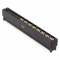

As a field engineer, I've seen countless issues with board-to-board connectors like the TE Connectivity 1761426-1, a 36-position dual-row female connector with a 0.100" pitch. While robust, its failure can bring an entire system down. The first step is always to visually inspect the connector and its mating header under magnification. Look for cracked housing, bent or corroded pins, solder joint issues (especially on the PCB side), and signs of contamination or flux residue. A common root cause is mechanical stress from improper mating/unmating, leading to cracked solder joints or deformed pins that lose contact.
A systematic debugging methodology is crucial. First, verify physical installation: ensure the connector is fully seated and oriented correctly (note the polarization key). Next, with power off, use a multimeter in continuity mode to check for shorts between adjacent pins, especially on power rails. Then, perform a connectivity test from the connector pin to the corresponding trace or via on the PCB to rule out broken solder joints. With power applied, use a multimeter to check for correct voltage levels on power pins. For intermittent faults, gently wiggle the connector and board while monitoring signals with an oscilloscope; this often reveals cracked joints or poor contact. Finally, inspect the mating header for identical issues, as damage is often symmetrical.
Schematic and layout mistakes are frequent culprits. A common error is forgetting to tie unused pins on the connector to ground or an appropriate logic level, leaving them floating and susceptible to noise. In the PCB layout, insufficient support under the connector body can lead to flexing and broken solder joints during mating. Ensure the footprint matches the datasheet exactly—a misplaced pad by even a few mils will cause misalignment and stress. Also, provide a robust ground connection and consider adding mounting holes or stiffeners near the connector to absorb mechanical force. Another oversight is not providing adequate clearance for the mating connector's housing, leading to physical interference.
Verifying authenticity and quality is paramount, especially with common parts targeted by counterfeiters. First, purchase only from authorized distributors. Physically, compare the component to a known-good sample or the official datasheet. Check the molding quality—authentic TE connectors have sharp, clean logos and markings, with no flash or uneven surfaces. The contacts should be uniformly plated with a bright finish. You can also use X-ray inspection to verify internal pin alignment and solder ball presence (if applicable). For a definitive check, some distributors and TE Connectivity itself can provide batch tracing.
Effective measurement requires the right tools. A high-quality digital multimeter (DMM) is essential for continuity and voltage checks. An oscilloscope is needed to diagnose noise, signal integrity issues, or intermittent dropouts on data lines; use it to probe signals directly on the connector pins if possible. A milliohmmeter or a DMM with a good low-resistance function can measure contact resistance, which should be stable and low (typically well under 20 milliohms). For thermal issues due to high current, a thermal camera can identify overheating pins. When probing, use fine-point tips and be careful not to short adjacent pins.
Deciding between a faulty component and a circuit problem hinges on isolation. If the issue is localized to one pin or a symmetrical pair, suspect the connector or its solder joint. If an entire bank of pins fails, suspect a schematic or layout issue (like a missing power connection). Swap the suspect connector with a known-good one from a trusted source. If the problem moves, the connector is at fault. If it persists, the issue is in the PCB or the mating component. Also, test the connector in a different board socket if available. Intermittent problems that occur with physical manipulation almost always point to a mechanical failure in the connector system.
In one real-world case, a customer reported intermittent data corruption on a communication bus. Wiggling the board made it worse. Inspection revealed a barely visible crack in the connector housing near the mounting ear. This allowed the entire connector to flex slightly during operation, breaking contact on several pins. The root cause was an out-of-spec mating header from a different supplier that applied uneven stress. The solution was to replace both connectors with verified parts and add a support bracket.
Another case involved a new board failing power-on tests. Resistance checks showed a short between a 3.3V pin and ground. Thermal imaging localized heat to one pin on the connector. The fault was not the connector itself, but a tiny solder bridge underneath the connector body, hidden from view, caused by an over-enthusiastic reflow profile. This highlights the need for proper stencil design and inspection, especially for fine-pitch connectors. Reworking the solder joint resolved the issue, and adjusting the stencil aperture for the connector pads prevented recurrence.