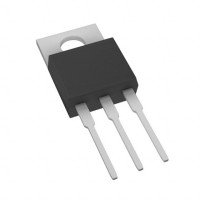

In this hands-on design tutorial, we will leverage the Panjit International ER1004CT, a classic TO-220AB package rectifier diode, as the cornerstone of a robust linear power supply. This component is an ideal teaching tool because it embodies the critical real-world considerations of power electronics: managing heat, understanding safe operating areas, and interfacing discrete semiconductors with control circuitry. The TO-220AB package is ubiquitous, easy to handle for prototyping, and its thermal characteristics force us to confront the practicalities of power dissipation head-on. The ER1004CT itself is a 10A, 400V dual common-cathode diode, perfect for constructing a full-wave rectifier in a compact form.
Our design goal is to create a bench-top linear DC power supply with a variable output from 1.25V to 15V DC, capable of delivering up to 1.5A continuously. The key specifications derived from this goal are an input from a 12VAC transformer (providing roughly 17V peak after rectification), a linear voltage regulator stage, and comprehensive protection. The rectifier stage must handle the transformer's inrush current and provide a smooth DC bus for the regulator. We will design for a worst-case scenario where the regulator drops maximum voltage at maximum current, ensuring all components, especially our TO-220 diode, remain within their limits.
The step-by-step design begins with the transformer and rectification. A 12VAC (RMS) transformer yields a peak voltage of 12V √2 ≈ 17V. We'll use the ER1004CT in a full-wave center-tapped configuration, which is highly efficient for this transformer type. The first critical calculation is the peak repetitive current the diode must handle. Assuming a 1.5A DC load, the average current per diode in this configuration is half the load current, but the peak current will be higher. We must consult the diode's datasheet for its IFSM (surge current) rating to ensure it can withstand the transformer's turn-on surge, which can be an order of magnitude higher than the operating current. Next, we calculate the worst-case power dissipation in the diode: P_D = V_F I_AVG. With a typical forward voltage (V_F) of 0.95V at 3A (from the datasheet) and an I_AVG of 0.75A, dissipation is a low 0.71W. However, we must also design the heat sink for the scenario where this diode and the subsequent linear regulator are both dissipating significant heat.
For the complete Bill of Materials (BOM), component selection is driven by our calculations and derating for reliability. The ER1004CT is selected for its current and voltage headroom (10A/400V vs. our ~1.5A/17V), providing a comfortable safety margin. The transformer is chosen as a 12VAC, 3A unit to give overhead. We select an LM317 adjustable voltage regulator in a TO-220 package for its versatility and protection features. A 2200µF electrolytic capacitor filters the rectified output, with its voltage rating derated to 25V or 35V. Two ceramic capacitors (0.1µF and 10µF) are placed at the regulator's input and output for stability. The potentiometer for voltage adjustment is a 5kΩ multi-turn type for precision. A 1N4007 diode is added across the LM317's input-output to protect against reverse voltage. Crucially, we include a TO-220 heat sink with a thermal resistance low enough to keep both the regulator and rectifier junction temperatures below 125°C under full load, considering their combined dissipation.
Before building, simulation provides valuable insight. Use SPICE models for the ER1004CT (or a generic diode with similar V_F) and the LM317. The key simulations to run are: transient analysis to observe the rectified waveform and inrush current, and DC operating point analysis to check power dissipation in the diode and regulator under min and max output voltages. Pay close attention to the peak currents through the diode and the voltage ripple on the main filter capacitor. This will validate your capacitance choice. Also, simulate a short-circuit event at the output to see how the current limiting of the LM317 behaves, though remember the simulation won't capture the thermal dynamics that are paramount in the real build.
When building the prototype, adopt a methodical approach to managing high-current paths and heat. Use a perfboard or prototype PCB with wide traces for the main current-carrying paths from the transformer secondary, through the rectifier, to the filter capacitor and regulator. Securely mount the ER1004CT and LM317 to the same heat sink using thermal paste and insulating washers if the metal tabs are at different potentials (they often are). Before connecting the transformer, use a multimeter to check for short circuits. Initial testing should be done with a current-limited bench power supply in place of the transformer, or with a fuse in series with the transformer primary. First, verify the rectified DC voltage at the filter capacitor. Then, with a dummy load resistor (e.g., 10Ω/10W), test the output voltage adjustment range.
Performance verification involves thermal measurement under full load as the ultimate test. Apply a 15V, 1.5A load (a 10Ω power resistor) and let the system run for 30 minutes. Use a thermocouple or IR thermometer to measure the heat sink temperature near the diode and regulator. The case temperature should be well below the maximum specified, indicating a safe junction temperature. Use an oscilloscope to measure output voltage ripple and noise. Optimization may involve adjusting the filter capacitor value to reduce ripple further or improving the heat sink if temperatures are too high. Finally, test the current limiting by progressively lowering the load resistance until the output voltage drops, confirming the regulator's protection is active. This end-to-end process, centered on a robust TO-220 component, solidifies the critical link between theoretical design, simulation, and physical realization in power electronics.