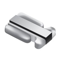

Today we're designing a high-current sensing circuit using the Bourns CST0612-FC-R0015E, a 1.5 milliohm, 1% tolerance, 1-watt current sense resistor in a compact 0612 package. This component is an excellent choice for a hands-on tutorial because it forces us to confront real-world challenges in precision, high-current measurement. Its extremely low resistance minimizes power loss and voltage drop in the current path, but it also produces a very small signal that is susceptible to noise, thermal drift, and layout-induced errors. Successfully implementing this resistor teaches critical skills in low-value signal conditioning, PCB layout for precision circuits, and thermal management.
Our design requirement is to create a circuit that can accurately measure a DC load current up to 25A, with a target accuracy of better than 2% across an ambient temperature range of 0°C to 70°C. The output should be a clean 0-3.3V analog signal compatible with a microcontroller's ADC. Key specifications include a bandwidth of DC to 10kHz to capture potential transient events, and the circuit must operate from a single 12V supply rail. The primary challenge is amplifying the tiny 37.5mV full-scale signal (25A * 0.0015Ω) up to a robust 3.3V level, a gain of approximately 88, without introducing significant offset, noise, or thermal error.
The step-by-step design process begins with the amplification stage. We need a precision differential amplifier to reject common-mode noise. A dedicated current sense amplifier IC is the most practical choice. For this design, we'll select the INA240A2, which offers a fixed gain of 50 V/V, excellent common-mode rejection (120 dB), and a wide common-mode input range that includes our 12V supply. With the INA240's gain of 50, our 37.5mV sense voltage becomes 1.875V. A second op-amp stage is required for further amplification and level shifting. We'll use a general-purpose precision op-amp like the OPA2180 in a non-inverting configuration. The required additional gain is 3.3V / 1.875V = 1.76. We'll set the gain to 1.8 using 1% tolerance resistors, providing a slight margin. We must also add a simple RC low-pass filter at the output with a cutoff frequency around 15kHz to limit noise.
The component selection rationale extends beyond the amplifier. The BOM must support precision and stability. For the INA240 and OPA2180, we need high-quality, low-ESR decoupling capacitors: a 0.1µF ceramic placed as close as possible to each supply pin, paired with a bulk 10µF tantalum or ceramic per rail. The gain-setting resistors for the second stage must be 0.1% tolerance, low-temperature-coefficient (25ppm/°C or better) metal film types to maintain accuracy. The power connector and PCB traces carrying the high current are critical components themselves; we must use thick traces or poured polygons, and the resistor must be placed in a 4-wire Kelvin connection layout. This means the high-current path flows through the main resistor pads, while separate, delicate sense traces connect directly to the resistor's inner terminals to measure the voltage drop without including the voltage drop of the solder joints or PCB traces.
For simulation, focus on three key areas using a SPICE-based tool. First, simulate the DC transfer function to verify the overall gain and output voltage range across the full input current. Second, run a transient analysis with a stepped load current to ensure the amplifier outputs do not saturate and the recovery from overload is clean. Third, and most importantly, perform a noise analysis. The tiny input signal is vulnerable; the simulation will show the output noise density and help confirm that your output filtering is adequate to keep noise below your ADC's resolution. Pay close attention to the simulation results for the amplifier's input offset voltage, as even a few microvolts of offset will create a significant current reading error at this scale.
The prototype build demands meticulous attention to PCB layout. Use a 4-layer board with dedicated ground and power planes. Isolate the analog ground plane from the noisy high-current power ground at a single star point. Implement the Kelvin connections for the sense resistor as described. After soldering, visually inspect the resistor joint under magnification—excess solder can change the effective resistance. For testing, begin with a low-current bench power supply and a precision digital multimeter. Use a known accurate shunt resistor in series with your load to calibrate your circuit. Gradually increase the current from 1A to 25A, comparing your circuit's output voltage to the calculated value from the reference shunt. Log the error at multiple points to calculate linearity.
Performance verification involves testing across temperature and dynamic conditions. Use a thermal chamber or a controlled heat source to monitor output drift from ambient to the maximum specified temperature. The thermal performance of the Bourns resistor itself is crucial; at 25A, power dissipation is I²R = (25)² * 0.0015 = 0.9375W, very close to its 1W rating. You must have sufficient copper pour on the PCB to act as a heat sink, or the resistor's temperature rise will increase its resistance (the CST0612 has a 50ppm/°C TCR). Finally, optimize by adjusting the output filter's cutoff frequency based on your actual noise measurements and required bandwidth, and fine-tune software calibration coefficients in your microcontroller code to nullify the measured offset and gain errors, achieving the final system accuracy.